
LED strips are a DIYer’s dream come true. Believe me, I’ve gotten sucked into binge watching hours of LED project videos more than a few times.
Even though I found tons of really good ideas (and wasted many hours), I struggled to find one place where I could get all the information I needed to create my own project.
That’s what this guide is for.
This guide is meant to take you from complete beginner to finished project.
I will teach you how to select and install the right LED strips for your application. I will also teach you how to select and install the appropriate controllers and power supplies to match your LED strips. And along the way, I will answer common questions and share what tips I’ve learned.
Finally, at the end is a list of my recommended products for your LED strip project.
[adinserter block=”6″]
Types of LED strip chips
If you’re shopping for LED light strips, you’re likely to come across all kinds of letter and number combinations that are supposed to describe the strip you’re looking at.
What do the letters mean?
The letters in the description refer to the output color(s) of the LED chips on the strip.
If the letters are separated by a “+” or a space, it usually means that they are separate chips. If there is no space, it usually means they are all integrated into one chip.
When the LEDs are on separate chips, fewer lights can be packed into the same length strip.
RGB – Red, Green, Blue
An RGB LED contains three diodes (LED stands for Light Emitting Diode) on the same chip: one for each color. Each color is wired to its own channel. By adjusting the power delivered to each color (using a controller), any combination of colors can be created.
W – White
Typically a single “W” refers to a pure white (6500K). There’s no set standard so make sure to double check.
WW – Warm White
Warm white is usually 2700K, similar to the color of an incandescent bulb.
CW – Cold (or cool) White
Cold white is in the 6500K range, but check to be sure.
CCT – Color Correlated Temperature
CCT usually means that the strip includes two channels of white. One is a warm white and the other is a cool white. By adjusting the power delivered to each white channel, the strip can produce any white light equal to or in between the two LEDs. The CCT LEDs can either be both on the same chip or on separate chips.
Examples of common LED chip configurations:
| Label | Description |
| RGB | A single 3 channel chip with RGB LEDs |
| RGBW | A single 4 channel chip with RGB and white LEDs |
| RGB+W | One 3 channel chip with RGB LEDs and a separate single channel chip with white LED |
| RGB+CCT | One 3 channel chip with RGB LEDs and a separate 2 channel chip with cold white and warm white LEDs |
| RGBCCT | A single 5 channel chip with RGB, CW, and WW LEDs |
What do the numbers mean?
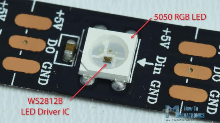
An LED strip description often includes a 4-digit number such as 5050 or 2835. The number usually describes the size of the chip.
For example, a 5050 LED chip measures 5.0 mm wide by 5.0 mm tall. Similarly, a 2835 chip measures 2.8 mm wide by 3.5 mm tall.
If you are looking at a digitally addressable strip, you will likely see a four digit number (for example, WS2812B or SK6812). But in this case, it has nothing to do with chip size. Instead, the number is the name of the integrated LED controller chip.
| Common addressable LED controllers: |
| WS2811 |
| WS2812 ECO |
| WS2812B |
| WS2813 |
WS2815 |
| SK6812 |
| SK9822 |
Does size matter?
Although most equal sized chips have similar characteristics, not all chip manufacturers are created equal. Therefore, there’s no guarantee that chips of the same size from different manufacturers have similar performance.
Generally a larger chip is brighter, but not necessarily. Ultimately, several factors determine the overall brightness including the chip circuit design, power consumed, and materials used.
For example, below is a table with basic specifications for three different chips made by Epistar (a popular LED manufacturer).
| LED | Chip Surface Area | Luminous Flux | Power consumed |
| 2835 | 9.8 mm2 | 22-24 lm | 0.2 W |
| 5054 | 27 mm2 | 45-55 | 0.5 W |
| 5630 | 16.8 mm2 | 50-60 lm | 0.5 W |
Notice how the 5630 puts out more light than the 5054 even though it has less surface area. Also, it manages to put out more light while still using the same amount of power (more efficient).
Size does play a role in determining how many LEDs can be mounted on a strip:
1. A narrow chip can be mounted to the strip more closely together creating a more uniform light.
2. A large chip can potentially fit multiple diodes on the same chip. This can allow for a better spacing for multi-purpose (color-changing) strips.
For example, an RGBCCT chip has 5 total diodes on one chip. The same chip is used continuously throughout the strip. Each chip can create colors and whites.
Compare that with an RGB+CCT strip. Two different chips are used. One creates colors and one creates whites. They are arranged alternately.
The distance between each similarly colored LED is greater on the RGB+CCT strip compared to the RGBCCT strip. In practice, the bigger gap can make the light less uniform.
How to choose the right LED strip
There are seemingly endless variations of LED strips that are being sold in a wide price range. What are the differences between cheap and expensive? And, what is best for your project?
Brightness
Brightness or luminosity is usually measured in lumens. For LED strips, the question you are interested in is, how bright is my strip per unit length? So rather than a total lumen amount, you should be looking for lumens/foot or lumens/meter.
Here are some guidelines for choosing a brightness level depending on the situation.
| Use | Suggested Lumen/foot |
| Accent/Mood lighting | 150-350 |
| Under cabinet lighting | 175-525 |
| Task lighting (close) | 275-450 |
| Task lighting (far) | 350-700 |
| Indirect lighting | 375-575 |
| Fluorescent tube replacement | 500-950 |
It’s a good idea to buy strips with extra brightness for your application. Then, get a dimmer to reduce the brightness to the desired level.
Using a dimmer will lower the operating temperature of the LEDs which will lengthen their lifespan.
Furthermore, as LEDs age, they do lose some of their luminosity. If you oversize your LEDs a bit from the beginning, you will have some extra brightness to make up the difference as they age.
Efficiency
Luminosity doesn’t always tell the full story. You can get more brightness out of any LED if you pump enough power through it, but that’s not always a good thing.
An LED strip manufacturer can increase the reported lumen output by overpowering the LEDs. This will cause them to shine more brightly, but will also cause them to get hotter and run less efficiently. Since heat is the main reason for an LED to fail prematurely, it’s likely that overpowered LEDs will not last as long as they otherwise could.
For that reason, it’s good to ask the question, how much light does it put out compared to power used? This ratio is called the luminous efficacy. It’s often listed in a products specs. If not, you can calculate the efficacy by dividing the number of lumens produced by how much power it uses.
Do I need a high CRI light?
Color rendering index (CRI) is a measure of how accurately an artificial light source replicates natural light. It is reported as a number from 0-100.
A CRI greater than 80 is acceptable for most applications.
A CRI greater than 90 is considered high CRI and is mainly used in retail, art, film, or photography. Some of the best quality LED strips have a CRI of 97-99.
Why is CRI important?
Objects under low CRI lighting may seem dull or harsh depending on the light and color. Colors will be less vibrant and the overall lighting effect will seem less bright.
But why is that?
NOTE: What follows is a technical explanation of what makes a high CRI light. You can skip it if nerdy stuff makes your eyes glaze over.
Light that we can see is usually not made up of a single wavelength. Rather, it’s a collection of waves that span the visible spectrum. The color the light appears to be is an average of the included waves.

As shown in the image above, different wavelengths correspond to what we see as different colors. The color of an object will be determined by the wavelengths of light it reflects.
For example, if the sun shines on an object and we see red, that means the object has absorbed all the wavelengths of light except for the light in the red wavelength region. That light gets reflected into our eyes causing us to see a red object.

Now what happens if instead of sunlight, we shine an LED light on the apple?
Well, if it’s a standard, low-cost LED, the result will likely be a dull, orangish and generally unappealing apple.
Why?
Sunlight at noon has a correlated color temperature (CCT) of 5500-6000K. You might think that in order to replicate daylight, you just need to buy an LED with the same CCT. But, it’s more complicated than that.
Any visible light can be broken down into its parts by measuring the power of the waves in a given wavelength range. This is often shown in graph form using a spectral power distribution graph. Below is a spectral power distribution graph of daylight.

A typical LED has a spectral power distribution graph that looks something like the image on the left. Notice there are significant deficiencies around the cyan and red areas. This will cause objects that include those colors to look “off” when viewed under these lights.
A high CRI LED has a more even spectral power distribution like the image on the right. This particular one is made by YUJILEDS.


Below is the same YUJILED compared to daylight (white dotted line).
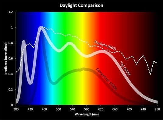
An LED light can be built to give off a CCT of 6000K (to match daylight). But if the spectral power distribution doesn’t closely match natural light, objects will always look “off” when viewed under the light.
Is 12V or 24V Better?
LED strips are most commonly available in either 5V, 12V, or 24V.
For analog strips, most people will choose either 12V or 24V. Generally, 12V is perfect for small installations, but for large installations, it may be better to go with 24V.
For projects with digital strips, it can sometimes be convenient to use 5V strips. Most digital controllers run on 5V which allows the controller and the strips to be run from the same power supply. Furthermore, on 5V strips each individual LED can be independently controlled.
Higher voltage means longer runs
A higher voltage strip will generally be able to have longer runs without suffering from the effects of voltage drop.
What is voltage drop?
Voltage drop causes LED strips to lose their intensity as the strip becomes longer. LEDs at the beginning of the strip (nearest the power supply) will shine brightly. Whereas, LEDs at the end of the strip will have a dimmed appearance.
An example of voltage drop
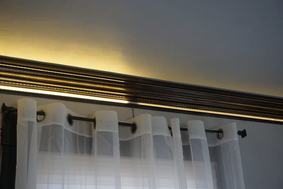
Above is a great example of the effects of voltage drop.
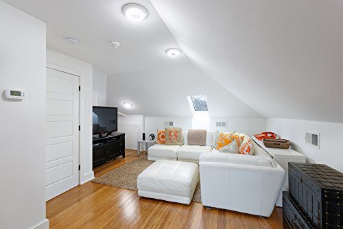
A couple years ago, I installed some indirect lighting in my living room. I used 12V strips and made a loop around the perimeter of the room by connecting three 5m strips end to end to one power source.
The bright light on the left is the start of the strips. The lights travel around the room and end right next to the beginning. The lights on the right side are suffering from voltage drop and are much less bright.
Why does this happen?
Any length of wire has a certain amount of electrical resistance. The longer the wire, the more the resistance. Electrical resistance causes voltage drop and voltage drop causes your LEDs to dim.
Therefore, LEDs at the end of a strip will always be getting less voltage than the LEDs at the beginning. If you make the strip long enough, the drop in voltage will become significant enough to cause a visible difference in brightness.
How does higher voltage reduce the effects of voltage drop?
First, you have to have a basic understanding of how all the components on an LED strip are connected.
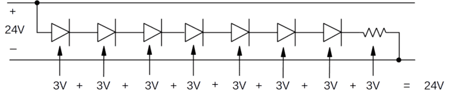
Most individual LED chips run on 3V DC power regardless of whether they are mounted on a 12V strip or a 24V strip. In fact, the same LED chip that works on a 12V strip could also be mounted on a 24V strip. What makes the difference is how the strip circuitry is designed.
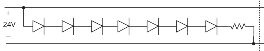
LED chips are wired in series into groups. Each group contains some LED chips and a resistor. The total voltage drop across the group has to be equal to the total voltage of the strip (see diagrams below).
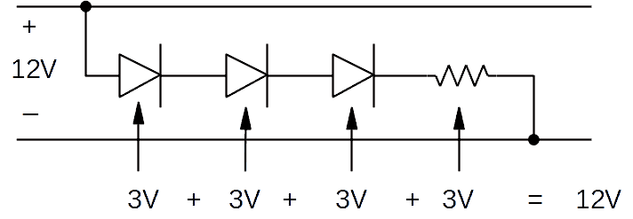
Then, each of the groups is wired in parallel and arranged along the length of the strip.
For now, take notice (above diagrams) that the group size on a 24V strip is 7 LEDs compared to only 3 LEDs for 12V. I will explain why this is significant below.
Every wire has a certain amount of resistance to electricity being pushed through it. The longer the wire gets, the bigger the resistance (and the voltage drop) gets. Eventually it gets large enough to impact the LED brightness. Below is an example of how it might happen on a 12V strip.
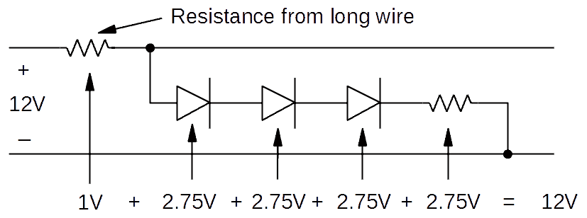
Notice in the above diagram that the voltage across the LEDs has dropped from 3.0V to 2.75V.
When we switch to 24V, two things happen that reduce the amount of voltage drop.
- When the voltage gets doubled (12V to 24V), the current is halved (Ohm’s law). That causes the voltage drop from the long wire to be reduced by half as well. So instead of a 1V drop, it becomes 0.5V drop.
- The effect of the 0.5V drop is split between the 8 remaining circuit components (compared to 4 on the 12V).
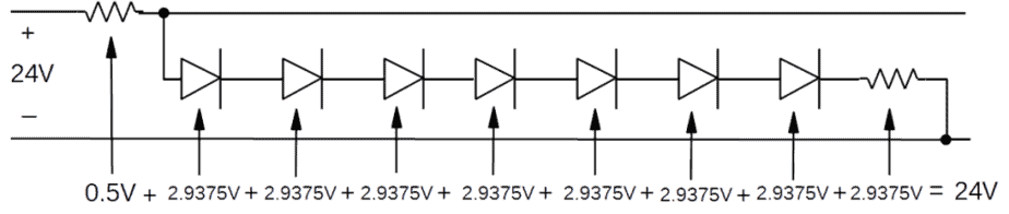
Notice here that the voltage across the LEDs has only dropped to 2.9375V compared to 2.75V with the 12V strip.
If you have an application that requires long runs of strips, it may be a good idea to us 24V strips. But, even 24V strips have a limit. You may have to use other techniques (see power section below) to stop your LEDs from fading at the end.
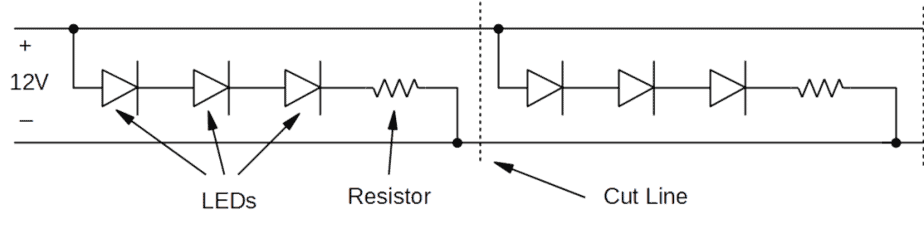
Lower voltage has Closer Cut Lines
As I just mentioned, LED Strips are wired in groups of LEDs. The size of the group depends on the voltage of the strip. A 5V strip will only have one LED per group, a 12V strip has 3, and a 24V strip has 7.
The cut lines are located between the groups. Therefore, the smaller each group of LEDs, the closer together the cut lines can be.
For example, see the diagrams of 12V and 24V strips below.
If your installation has many corners with short lengths between, a lower voltage strip with closer cut lines may be a good choice. This can help to minimize the “dead” spots at the corners.
Higher voltage can be more efficient
Any time there is voltage across a resistor, it means energy is getting converted to heat instead of light. Therefore, the resistors in the above diagrams are necessary, but they’re also a source of wasted energy.
How much is wasted?
The calculation is fairly simple. All we have to do is divide the amount of voltage across the resistor by the total voltage:
| Total voltage of strip | Voltage across resistor | % Power “wasted” on resistors |
| 5V | 2V | 40% |
| 12V | 3V | 25% |
| 24V | 3V | 12.5% |
It’s easy to see that higher voltage strips suffer from less wasted energy. LED’s use such a small amount of energy that this doesn’t add up to much for small installations. But, for whole room or commercial installations, the difference in power usage can become significant.
How thick is the copper?
The flexible strip that the LEDs are mounted on is actually a circuit board. Within the strip, there is a layer of copper that provides the electrical circuitry and the bulk of the heat dissipation.
For those reasons, the thickness of the copper layer matters.
A thicker layer of copper means electricity can flow through more easily (less electrical resistance). This will create less voltage drop and allow longer runs.
It will also dissipate heat more quickly. The LEDs will stay cooler, which will ultimately help to maximize their lifespan.
The amount of copper in an LED strip is usually measured in ounces per square foot. Typical values for an LED strip are 1oz-4oz. Higher power requires more copper.
Unfortunately, very few retailers list this on the product info page. If you’re planning a small project with some bargain level strips, I wouldn’t worry too much about it.
However, if you are planning a big project with high-quality strips, it would be worth contacting the manufacturer if it isn’t listed on the specs page.
How to install LED strips
The best way I’ve found to install LED strips is within an aluminum channel.
The channels are available either angled or flat, and with a diffuser cover or clear cover. They do come in different widths, so make sure the channel fits the strip.
You can cut the soft aluminum channels with a hacksaw or with an electric miter saw. If you use the miter saw, you should use a carbide tipped blade with lots of teeth.
Once cut to length, the channel can be firmly mounted using screws.
Benefits of installing LED strips inside a channel:
- Provides a uniform surface for the strip’s adhesive to form a secure, long-lasting bond.
- The aluminum acts as a heatsink and helps to dissipate heat for longer LED life.
- The plastic cover will diffuse the light. This will make the light from the LEDs appear more uniform.
- The cover will also help to protect the strip from dust and damage.
- If the LED strips are in plain view, the clean lines of the channels help to give the installation a more polished look.
Despite all the great benefits of the channel, there are installations where the extra cost of the channels just isn’t worth it.
The biggest problem you’ll have when installing without a channel is the strip’s adhesive not holding. It will usually stick initally. But sometimes a week or a month later, the adhesive will fail.
In order to make sure the adhesive doesn’t work its way loose, I recommend using a dab of hot glue every couple feet.
How to connect LED strips
Soldering is usually the most reliable method for joining two LED strips. But, it’s also time consuming, requires special equipment, and requires a bit of skill.
Clips are faster and don’t require any skill. For that reason, I recommend using clips if you’ll have easy access to the strips (most installations).
However, the connections made by the clips are not as permanent as solder. They are vulnerable to corrosion and movement.
Therefore, I recommend using solder if the strips may experience:
- Weather – any outdoor installation, or heating and cooling that could cause condensation
- Movement – any sort of flexible channel or location that might experience vibration
- Very permanent – enclosed in epoxy or other similar
How to deal with corners
The challenge with corners is to effectively turn the corner without leaving a “light gap” and without spending too much time fiddling with cutting and connecting.
Gentle bend
The best way I’ve found for most of my installations is just to create a gentle bend around the corner.
For this method, you don’t need to cut the strip or have any special connecting hardware. You can do bends even if strip components happen to land right on the corner.
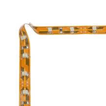
Guide the strip around the corner and let the strip take its own shape. The result will be a small loop in the corner.
One problem with this method is over time the adhesive in the corner can be pulled up. To stop that from happening, use some hot glue on each side of the corner.
If you are installing the strips inside a channel, the bent area may not fit inside. This is especially true for strips with densely packed components. In that case, I recommend cutting the strip and using the corner connectors instead.
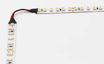
Corner Connector
You can also cut the strips at the corners and rejoin them with connectors. However, LED strips must be cut on their cut lines. Therefore if the gap between cut lines is large, you could end up having a small gap with no light in the corner.
This is an instance where installing the strips in a channel with a diffuser will be helpful. Without the diffuser, you will likely have a dim or dark spot.
You can buy rigid plastic 90 degree corner connectors, but I recommend the type with wires. The flexible wires can be adjusted to any angle.
Fold Method
You can try to fold the strips but I don’t recommend it. The PCBs on most LED strips are quite flexible. Make sure your bend will not put any stress on areas with any components. Low density single color strips work the best for folding because there’s more “clean” area available for a fold.
First, bend the strip at a right angle in the opposite direction of the turn.
Then, make a second bend by folding the bent end back over itself.
Remove LED strips
Once an LED strip is securely stuck to a surface, it can seem nearly impossible to remove it without destroying the strip.
Don’t just pull the strip and hope for the best. You will risk tearing the strip or damaging individual LED connections.
Instead, use floss.

No, not that kind of floss! Dental floss.
Cut a length of floss and slide it under an edge. Then, work it back and forth along the length of the strip.
How to power LED strips
LED chips are powered using DC (direct current). Therefore, you can’t plug an LED strip directly into the wall outlet (alternating current). Instead, you need a power supply to convert the AC power from the wall into DC power that the LED can use.
How to Select an LED Power Supply
This is an area that often gets overlooked especially among hobbyists. If you’re going to spend money, you probably want to spend it on some super bright, high-quality LEDs. Therefore, it’s tempting to cheap out on a power supply. But, spending the money up front on a good power supply will often pay for itself over time.
How much power do you need?
First, you need to know how much power your strips will use so that you can select a properly sized power supply.
Every vendor should list the power consumption of their LED strips. It may be listed as the power consumption of an individual LED chip or as the power per length of strip. Either way, just multiply the power per unit length by the total length of the strip you plan to use. That number will definitely be enough. However, in some cases it may actually be way too much due to how controllers manage your LEDs (this post explains more).
Don’t worry, it’s not necessary to get a perfectly accurate number. Close is good enough.
Once you have an estimate of the power usage of your strip, a good rule of thumb is to add another 20% (strip power / 0.8). Then, select a power supply that can provide greater than or equal to that amount.
The extra capacity will help to insure a long life for the power supply. As with LEDs, a common cause of power supply failure is heat. And running a power supply at full capacity will heat it up.
Power supply voltage must match the LEDs
The power supply must be the same voltage as the LED strip.
For example, if you try to use a 24V power supply on a 12V strip, the LEDs will shine very brightly (overpowered) for a short period of time. Before long, they will overheat and burn out.
Conversely, if you try to use a 12V power supply on a 24V strip, the underpowered LEDs will not light up at all.
Waterproof or not?
A power supply enclosure is usually rated using the IP rating system. The first number of the IP rating is protection against sold objects (e.g. fingers, dirt, dust). The second number is protection against liquid (e.g. dripping, spraying, immersion).
Waterproofing
If you’re looking for a waterproof power supply, I recommend making sure you get an IP67 or IP68. These are expected to be fully submersible.
You can also find power supplies with an IP65 rating marketed as waterproof. These are protected against water spray (e.g. heavy downpour, hose spray nozzle) but not submersion.
The price difference between IP65 and IP67-68 is usually minor, so the extra protection is worth it.
Dustproofing
Even if you’re not worried about water, you may want a sealed power supply to protect against dust.
Any power supply with an IP rating that starts with “IP6” will be sealed against dust.
If power supplies are open to the air, dust can accumulate on internal components. This contributes to excess heat build up which can shorten the life of the power supply.
Power supply efficiency
The efficiency of your power supply can make a big difference in total power usage. Typical efficiencies for power supplies run between 70% and 90%.
For example:
If I have an LED strip that uses 100W, a power supply with 70% efficiency will draw 100W/0.70 = 143W of electricity.
Whereas a power supply with 90% efficiency will only draw 100W/0.90 = 111W.
For the most part, if you want more efficiency from your power supply, you have to pay for it. Whether or not it makes sense to pay for more efficiency will usually depend on the size of your project.
Installing the power supply
If you plan to just plug your LED power into an existing outlet, you don’t need to worry about violating building codes. As long as you’re not tapping into mains voltage or running wires inside walls, you are in the clear.
However, if you’re doing a large installation, you probably don’t want wires hanging around everywhere. In that case, a clean install usually requires multiple LED driver power supplies and running wires through walls.
If you’d like to have a nice, clean look, consider putting all the power supplies inside an enclosure. Bring the line voltage into the enclosure and wire up an outlet within the enclosure. Then mount the power supplies and plug them into the outlet.
DO buy a class 2 rated power supply. If you are running wires within walls, this will make sure you don’t exceed power requirements. A class 2 power supply is limited to 60W for 12V and 96W for 24V.
A single power supply can exceed the power limit if it splits the power into multiple outputs as long as each output is within the power limits.
DO use class 2 compliant (CL2) wiring if you will be installing any wires inside finished walls.
DONT wire your power supply directly to line voltage. Instead, connect a 3 prong plug to the input (120V) side and plug it into an outlet.
DONT install the power supply inside a wall without an access panel. This should go without saying, but there’s always that guy. Power supplies do fail and if they’re stuck inside the wall, it becomes quite a maintenance headache.
How to power very long strips
If you have a long enough run of LED strips, you will experience voltage drop. You can reduce this problem by using higher voltage strips (as explained above), but that won’t solve the problem completely. Eventually, if the run is long enough, even a 24V strip will suffer the effects of voltage drop.
Fortunately, there are ways to extend the reach of your strips without too much trouble.
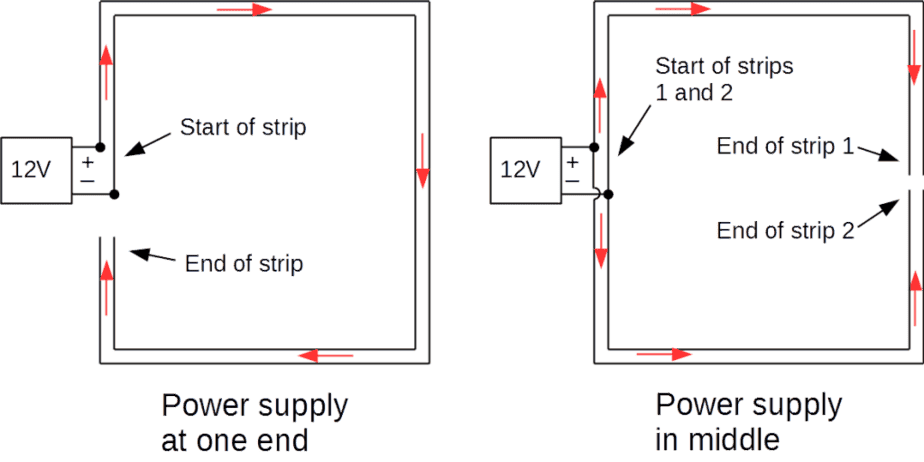
Install the power supply in the middle
The simplest way to double the effective length of your strips is to place the power in the middle of two strips. Similarly, if the strip makes a loop, you can connect both ends to the power.
Use power injection
Of course, sometimes you’ll be limited by where you can install your power supply. In other cases, you will have such a long run of lights that even placing the power in the center won’t be enough to avoid the voltage drop.
In those cases, you will have to run more wires to the locations that need it. This is called power injection.
Power injection can be done with one power supply or multiple power supplies. It’s done differently for analog and digital strips.
Power injection for analog LED strips
Analog strips don’t have embedded microcontrollers like the digital strips. That means that some kind of voltage controller needs to be installed between the power supply and the strip at all connections.
One option would be to buy a second controller. Essentially that would create a second LED strip with separate power and separate control. Then if you wanted to, you could use automation software to make sure the two controllers stay synchronized.
However, there’s a simpler (and cheaper) solution.
Signal Repeaters
A signal repeater can be connected anywhere that power injection is needed. The repeater will transfer the signal so that all LEDs are synchronized by a single controller.
This way is simpler for home automation because only the one controller is added to the smart home network.
It also makes the wiring for power injection simple. All you need to do is connect power to the repeater and wire the two strips to the repeater.
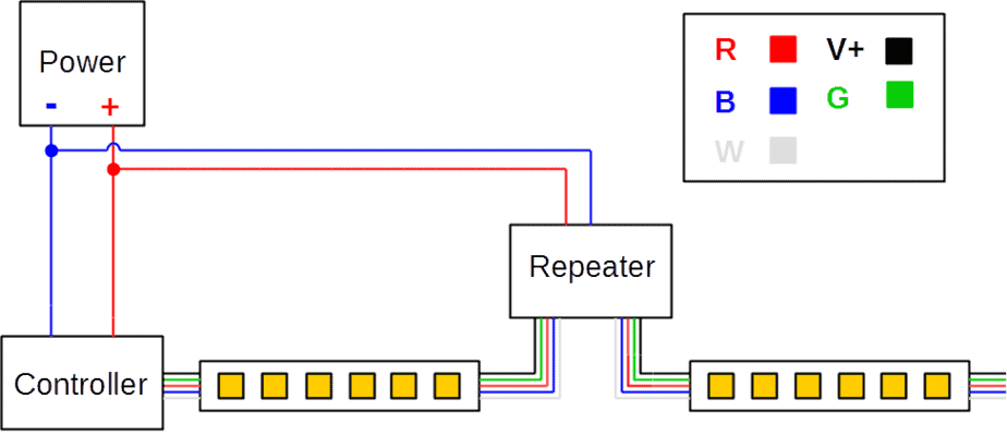
A repeater can be powered from the same power supply as the controller (above). Or, it can be powered from a separate power supply (below).
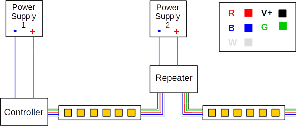
If needed, multiple repeaters can be used. The repeaters draw their own power allowing a single controller to be used for any length of strips.
Power injection for digital LED strips
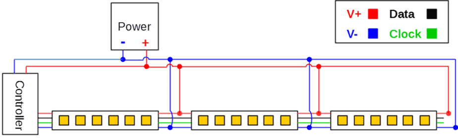
For digital strips, the voltage for each LED is controlled by microcontrollers mounted on the strip. The microcontrollers require the full amount of voltage from the power supply, so power injection is done by wiring the power supply directly to the strip.
With a single power supply, power can be injected by simply connecting the power supply wires to the V+ and V- wires wherever additional power is needed.
NOTE: Not all addressable strips require the “Clock” wire as shown in the diagrams. Whether it’s required depends on the type of microcontroller the strip uses.
With multiple power supplies, the technique is the same except that V+ is not connected between power supplies.
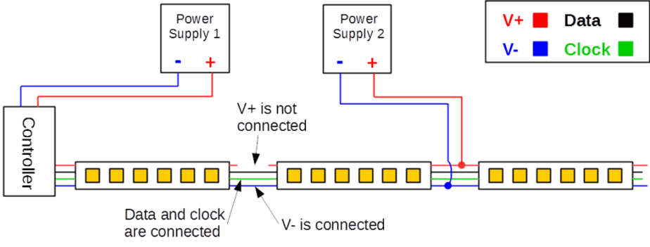
WARNING: Never connect the positive wires between power supplies. This can destroy power supplies and potentially start fires.
How to select the right wire size
Thick wire will have less voltage drop than a thin wire. Therefore, if you need to run wires for long distances, the thicker the better.
However, thick wire is more expensive. It’s more difficult to hide. And, if you are trying to fish wires through walls, thick and rigid wires can make your job quite difficult.
To select the right size wire, you need to know the:
- Strip Voltage
- Current – In order to calculate the required current, divide the total required power by the voltage. For example, a 100W 12V strip requires 100W/12V = 8.3A.
- Length of wire
- Acceptable amount of voltage drop
Then, plug in the values into this calculator. Adjust the wire size and recalculate until you get an acceptable amount of voltage drop.
If you will be installing the wires inside finished walls, the wiring should be labeled as class 2 compliant.
How to control LED strips
This section explains how to automate or wirelessly control the LED strips using smart home products.
Do I always need a controller?
If you have a single color LED strip, you wouldn’t necessarily need a controller. You could just connect it directly to a power supply.
Then, if you wanted to turn it into a smart light, you could plug the power supply into a smart plug. It works, but it’s very basic.
However, even if you don’t care about changing colors, most people will at least want the ability to dim. And in order to do that, you will need a controller.
How to dim LED strips
There are two common ways to dim LED strips using smart control.
The first way is to use a smart AC dimmer installed in the wall. In order to do this, the wiring goes from the dimmer switch to the power supply to the lights.
Pros/Cons of this method:
Con – You must have a dimmable power supply for this to work. These are usually more expensive than regular power supplies.
Pro – You can use any standard dimmer including smart dimmers like the Lutron Caseta dimmers.
Pro – When the lights are turned off, the power supply is turned off. This eliminates a source of “vampire” power.
Con – Only works with single color LED strips.
A second way is to use a smart controller. Here, the wiring goes from the power supply to the controller to the lights.
Pros/Cons of this method:
Pro – Smart controllers can control strips with multiple colors.
Pro – Doesn’t require a dimmable power supply.
Con – The lights are not wired directly to a wall control. In order to have control at the wall, it would require installing one of these extra smart switches at the desired location to communicate with the LED controller.
Con – The power supply is always on resulting in a source of vampire power.
This second method is my preferred way to do it. I’m a huge fan of color changing lights. Even if it’s in an area where I don’t need full color, I still want the ability to do white color shifting. I’m a big believer in using circadian lighting whenever possible.
How to control LED strip color
If your LED strips are color changing strips, you will need a smart controller.
Make sure your controller has enough channels. If you have an RGBW strip, you need a controller with 5 output terminals. One terminal is the supply voltage (V+). The other four terminals are for each of the R, G, B, and W LEDs.
It’s okay to use a controller with too many channels. However, be aware that there is a limit to how much current can run on each channel.
A controller has a limit to how much current can be ran through it. For example, this RGBGenie controller can handle up to x amps.
In most cases, voltage drop will cause problems long before your controller runs out of capacity.
Wireless protocols
A smart LED controller communicates with your smart home using some kind of wireless “language” (protocol). You have basically three protocols to choose from: WiFi, Zigbee, or Z-Wave.
If you don’t have any other smart home stuff, I recommend sticking with a WiFi controller. It doesn’t require an additional hub (uses your WiFi router) and tends to be cheaper than the other two options..
Zigbee and Z-Wave are both wireless protocols designed specifically for home automation. With one of these controllers, you can connect your controller to a smart hub like Samsung SmartThings and your automation possibilities will be endless.
I prefer the Zigbee protocol for my lights because it works with the Philips Hue hub. The Hue hub is very reliable and has super fast reaction times. Plus, I already have a bunch of Philips Hue lights so my Hue mesh network is strong.
NOTE: If you want your controller to be compatible with Hue, you have to make sure it’s a Zigbee 3.0 certified controller.
Where to install the controller
Controllers are usually much smaller than power supplies so they are easier to hide.
In most installations, it makes sense to install the controller as close to the strips as possible.
If necessary, run heavy gauge wire from the power supply to the controller to minimize voltage drop. Then switch to lighter gauge wire from the controller to the strips.
How to control individually addressable LED strips
For analog strips, all LEDs of the same color are wired to a single channel. A single controller can adjust the power to each channel independently, but cannot adjust the LEDs individually.
Addressable LED strip control is very different from analog. I am far from an expert in setting up addressable LED strip controls. However, the basic requirements are as follows:
- In order to use digital control, you must first have a digital LED strip.
- In addition, you will need a computer (many people use an Arduino or a Raspberry-Pi) to process code and send the signal to the LED microcontrollers mounted on the strip.
- Finally, you will also need to supply the computer with a program that tells the microcontrollers how to run the lights.
Once you add the ability to be able to control each individual LED independently of others, you can create much more powerful effects. Marlon at hometechhacker.com has this cool page showing what is possible with a little tinkering and a super-cool program called WLED. In addition, he has a few other articles that explain in more detail about how to set it up.
Recommended Products
Do a Google search for LED strips and you will get pages of results with countless vendors selling their strips and accessories.
There’s so many that I can’t say which ones are best. But, I can tell you which ones I’ve used and whether they worked for me.
As I continue to buy and test items, I will keep this list up to date.
LED Strips
High CRI (Daylight White) – MARSWALL LED Strip CRI 97+
RGBW – BTF-LIGHTING 16.4ft RGBW 4 in 1 LED Strip
LED Controllers
WiFi
Z-Wave
Works with Hue – GIDERWEL Zigbee RGBW LED strip controller
Power Supplies
Class 2 (CL2) – 12V 60W Power supply
Dimmable – HitLights 12V 60W dimmable LED driver
Final Thoughts
When I called this the “Ultimate Guide to LED Strips”, I meant it. I want this to be the biggest, baddest guide that will get you from zero knowledge to finished project.
But, I’ll admit that I don’t know everything there is to know about LED strips and this guide isn’t perfect. So, if you have any tips or things I missed, please let me know in the comments below and I’ll add it to the guide.
Thanks for reading!

I have been trying to find an answer for weeks w/ no luck. I have 12v rgb+w strips, 5m (x3). I know I need power injection. My question is, on this 5 conductor strip… what pins do I wire for power injection? The strip is labeled + R G B W… I know I wire (+), but what else?? Zero diagrams anywhere that I’ve found.
You have an analog LED strip so what you need is a signal repeater. Please see the two diagrams under the heading “Power injection for analog LED strips”.
Hi,
I’m planning on using individually addressed LEDs for lighting in a camper van. I’m playing around with WLED, which allows patterns – I call it my digital fireplace.
Problem is when someone gets up at night I want a motion detector to notice and turn on floor lights very gently. Just enough to turn on. However my WS2823B strip only dims 1/3rd of the way before shutting off. Otherwise it’s as bright as always.
Is there a different package that allows for such low light?
Hi and first thanks for your help. I’ve got two color adhesive 12v 4 wire led lights on my cart that display DRL and on off blinker which all sections on left are controlled by one controller, all sections on the right are controlled by an identical controller. This is because the DLR lights run with ignition on and turn off as the blinker activates the orange lights to indicate I’m turning. When the orange lights turn on, the white running lights turn off. This creates the turning indicator effect. These controllers are small roughly 3/4” wide, 1/6” thick and 2” long. Dimensions are estimated but real close. I short circuited one of the controllers and it won’t operate properly now. I know all these two electronic devices do is switch the ground from one color light to the other color, there by presenting a blinker effect in my golf cart. The problem is I don’t know what they are called or where to get one. A company out of Fla. called Liquid Lights installed the lights on my cart, now one of the (I call them controllers for lack of knowing what their really called. Your help is greatly appreciated. Thank you.Tom please return info to email.
I have seen mini-repeaters and full-sized (deck of card sized) box repeaters for RGBW lights and I was wondering if one is preferable over the other?
The minis are definitely easier to hide and the box ones have screws to avoid the need to solder, but is one type preferable over the other (more reliable, safer, etc) ?
(BTW, Both types seem to handle up to 4A per channel).
I haven’t used the mini-repeaters, but the box sized repeaters I’ve used usually can handle 6A per channel.
If you do go with the minis, I would at least make an effort to mount them so that air can get at all sides and would keep the current significantly below its design limit.
Question regarding controlling several RGBW zones:
Can I use a few (MiBoxer brand) WL5 controllers and a couple of B3 wireless remotes to control a few zones (or do I need additional hardware like a something besides a basic router and internet connection?) Basically trying to control zones via all the possibilities… ie: B3 remotes, an iPhone App, and thru Alexa.
BTW, I am not sure if those use the protocols you mentioned or not.
BTW, Great depth of info in your article.
Hey Eric, thanks for reading!
As far as I can tell the MiBoxer controllers and remotes are WiFi, so you should be fine with only a router.
For a large several zone home RGBW install, would you recommend a few large power supplies or many more smaller power supplies?
I thought larger would be better, but I have heard that smaller ones tend to be quieter (fan noise) and run cooler… but I am not sure if that is true or which is technically more efficient (on average).
You can use power supplies rated for outdoor use to have no moving parts so they operate silently, but at an increased cost up front
Looking to add LED strip lights on the interior and exterior of my yacht. Total of 3 zones (a future 4th). Since all existing lights are 12vdc, adding LED strips should be easy (just tap into the large battery bank via DC panel), no need for power supplies. The longest run would be just under 60 feet. If is use 12v RGBW strips how often do I need to inject power? Second question, what is you recommendation of controller? I’d like to have a wall mounted color wheel, but also be able to use a smart phone app.
Power injection requirements will depend on the strip. You’ll have to test it. If you can place the power at the center of the run (30′ on each side), you may be able to get by with none. As for a controller, I have had good results with RGBGenie products. However, I haven’t found a wall mounted color wheel control that is powered by DC. They do have a battery powered remote that could be mounted on a wall and might be a reasonable solution.
Hi Eric,
May I power a led power supply from old bulb wires in the ceiling?
I understand that when the switch is off the psu is not getting power at all but the 1.5mm conductor from old lights should be enough to power the new led PSU? What if need to use more than one?
Thank you!
Adrian
I got a power supply bundled in a box I bought at an auction. Do not know anything about it BUT would ike to know what it can do with LED strips. It is made by LED. It says S-100-12 Also it is #3219 if that helps. input is 115VAC 2.4A ……230VAC 1.2A 50/60Hz…..Output: +12V 8.5A…..What can I hook up to it? And can you point me in the direction of a tutorial?
I have a question. I would like to install led strip in my truck canopy. I would like to be able to use a manual switch to select either white light or red light. If I use rgb with white strip, would I need a controller? Could I just wire a switch to select red or white light. Thanks for the info.
That’s a cool idea, and yes that would work. You could even install a switch for each color and then use different combinations of on/off to create different colors. For example, turn on red only for pure red, turn on white and red for pink, etc.
HI Eric,
Your article on the Led stripes guide is very useful. I read it few times. I do have a project and is looks like this:
– I want to install 150ft of RGBW IP67 in my family room and control them with Zigbee as one very long stripe.
– Needs to be dimmable by phone ie Hue or Smartthings.
Here are my questions:
– Should I buy BTL led stripes RGBW 4 in 1, 12V or 24V? My guess is 24V
– Which connectors should I but? I guess 5 pin but which brand?
– Controler should be Giderwel Zigbee, dimmable, RGBW compatible. Issue is the current. based on specs 6A/channel, 15A max. If we used injector do we ignore the amp capacity of the controler or do I need to install many of them? If so, they won’t act as one anymore?
– Which injector should I take? So far I thought of BFT 5 pin 12/24V 24A
– How would the configuration diagram would look?
– What size of wire (AWG) should I select based on 12 vs 24V and distance and recommended configuration.
Thanks for the answers, since it will be an expensive project, I don’t want to blowout any piece of equipment…
Regards
-For 150 ft, I would lean towards 24V.
-For long analog strips, you add repeaters to extend the signal. The repeater both injects power and extends the signal. For a diagram of how this works read the section of this article labeled “Power injection for analog LED strips”.
-Wire size depends on your installation. Generally, the larger the better to minimize voltage drop.
hello, I don’t know if this is a dead thread, but I was wondering about led strips with the adhesive on the same side as the diode, I need it to point inward for a project.
I have never seen LED strips with adhesive on the front side. However, you could glue them down with a clear silicone sealant or hot glue.
Hi Eric, this is a great article. Thank you.
I’ve created a 12m loop using 5v digital strip (individually addressable LEDs). Not sure if this was wise but there you have it!
Power requirement at full brightness is 9w per metre (.3w per led, 30 LEDs p/m).
Am I right in thinking that a 5v, 30a (150w) supply is what is required to run this loop at full brightness? Can I get away with a smaller supply? 30 amps seems like a lot!
Also, am I correct to assume that I can simply connect a single power supply to both ends to avoid voltage drop?
Eric,
I have a different sort of LED question but you seem more knowledgeable then most so figured I would ask.
I am installing 2 24volt 450watt underwater LED lights on my boat. These are high powered so not many people have the correct know-how to figure out how to make this possible. I am plan on installing a 12volt to 24volt amplifier to give me the correct input voltage for the lights. There will be a RGBW installed but I was told I also need a booster to create enough power to operate the 900 total watts. Could you help with any input on this type of LED setup?
Thanks
I am not familiar with a setup like this. However, the power available doesn’t change much (you will lose a bit depending on the efficiency of your converter) when you change voltage. That said, you are going to need some serious power to keep those lights lit for any period of time.
Can you give me some advice? I have a switch that controls power to an outlet. I plug the power supply for my LED strip light controller into that outlet. When I flip the switch off, power goes off to the controller and I lose a connection with it, as expected. When I flip the switch on again, I am unable to get a connection with the controller again automatically. I have to run through the pairing steps again. Is there a better way to do this? I use 14 gauge wire from the switch to the outlet. Then I use 18 gauge wire from the LED controller to the LED light strips. Any advice would be appreciated.
Controller: https://www.amazon.com/gp/product/B07JPLVL6L/ref=ppx_yo_dt_b_search_asin_title?ie=UTF8&psc=1
Controller power supply: https://www.amazon.com/gp/product/B06Y64QLBM/ref=ppx_yo_dt_b_search_asin_title?ie=UTF8&psc=1
Yea, you don’t really ever want to cut power to your controller. What you need is a switch that doesn’t turn off the power when you flip the switch, but instead sends a message to a hub to turn your your controller on/off. I wrote about a few here Your controller is WiFi and I’ve never used that particular model so I’m not sure exactly what hubs it is compatible with. My preference is to use Zigbee for my controller. In my home, I am controlling some LED strips with a Zigbee RGBGenie controller and wall controller connected to my Philips Hue hub.
Very helpful. Just the info I needed without having to sit through a half-hour youtube video. Thanks.
Eric.
Thank you for the very informative article I hope you are considering a follow up. I’m sure you’ve probably come across quite a few questions to help with material.
You have answered most of the questions I have.
My remaining questions are comparability with regular lamps in output. Such as how many input watts for a group of led’s would it take to emit comparable luminosity with conventional florescent or standard bulbs within the same heat range or color index? Lets say 40 watt incandescent as a baseline or such as a standard 55/60 watt headlamp?
Thanks for writing this up! But one thing that jumps at me is this statement:
“When the voltage gets doubled (12V to 24V), the current is halved (Ohm’s law).”
This is the opposite of Ohm’s law : I = V/R
which says that current also doubles when voltage gets doubled.
You are correct. It would probably be more clear if I referenced the power equation (P = VI) first. Then, according to Ohm’s law, the reduced current in the wire will cause reduced voltage drop.
Hi Eric,
Be interested in your comments.
Having a cabinet made and 6 shelves (500mm wide) are going to have a strip LEDs to each for projecting light up and through bottles.
I am using a WiFi WL5 LED controller to control the RGBCCT strip and wondering if I treat each 500mm as a spur and wire all 6 in parallel whether I will have an impedance miss match when connecting them all into the WL5 controller??
https://www.aliexpress.com/item/32990957443.html?spm=a2g0o.productlist.0.0.5e04261ap47WFD&algo_pvid=f0d17521-a63e-4426-9351-0afd5199212f&algo_exp_id=f0d17521-a63e-4426-9351-0afd5199212f-1
Trying to get my head around if the strip LED which come as you know in sections which allows you to cut to length does some kind of buffering from section to section? If a controller wasn’t involved I would see a potential issue.
Just wondering if anyone else has been down this rabbit hole?
Wiring all 6 in series would be a PITA however it would take any impedance load miss match out the equation. 11 wire to strip connections verses 6 in parallel.
Cheers,
Ian
Great article thanks, however I’m trying to find a breakdown of the actual PCB wiring of the copper strip on a 12v strip section. I want to try wiring the components myself as I’m trying to fit them into a space too small for the width of the strip (inside a light up press button) so I’ll be using small copper wire. I’m using just one 5cm piece, I.e 3 LEDs and 3 resistors. Could you point me in the right direction?
Eric,
Great writeup! Can you further confirm or elaborate on my understanding on my particular desired setup, please? I am buying a reel of RGBWW to cut into 1 meter pieces for beside bathroom vanity mirrors (3M total). I’d like them to be able to be turned on with a wall switch (at whatever previous setting is fine), but also be able to be controlled for color, dim, etc. I’m OK with those settings to be behind the scenes (eg: in-app – likely MiBoxer) (though dimming at the wall would be nice). I understand that I need a power supply (in this case ~200W per vendor spec) and a separate controller. But is it possible to have it both ways (wall switch and app control), or does turning the wall switch off defeat the controller and thus result in the lights not coming back on with just the switch (eg: need to re-engage the controller)? If so, do you know of any workarounds?
Hopefully that makes sense.
Thanks much!
Shawn
Hi Shawn, the key is to use a controller that operates on an open protocol such as Zigbee or Z-Wave. For my LED strip setups, I am currently using Gledopto Zigbee controllers with RGBGenie Zigbee wall switches (my review). The RGBGenie switch replaces an in-wall switch and let’s you control power, color, dimming, and scenes at the wall. For app control, you just use whatever your Zigbee hub is, which could be Philips Hue, Echo Plus, SmartThings, etc.
Make sense?
Your discussion of what happens when you take into account the resistance of the long wire is not quite right. LED bulbs are not like passive resistors where V=IR. To a good approximation, the voltage drop across the LED bulbs is pretty much fixed. That is, current is zero until the “knee voltage” is reached, and then the current grows exponentially. (That is, the bulb goes from zero to full brightness with virtually no change in voltage.) Your diagram shows a 12V circuit with three bulbs having a knee voltage of 3V. Thus, the resistor would have 3V across it, and the current would be 3/R amps. R would be chosen to make the current right for the LEDs. If the resitance of the wire extension causes a 1V drop before in the circuit, then the voltage across the LEDs *is still* about 3V each, leaving only 2V across the resistor. This reduces the current throught the resistor (and hence the LEDs) by 1/3, and will result in a bigger effect than you might have expected.
Hey Mitch, thanks for the well thought out reply!
I remember getting stuck for a bit thinking about this when I wrote it. Now, I could be wrong, but I don’t think using the knee voltage to estimate the voltage across the LED is a good approximation either. If you take a look at the power curve of a typical LED used in LED strips, current still flows at voltage significantly less than the knee voltage (which makes sense, otherwise how could the lights be dimmable?).
That said, I realize my example is not perfectly correct and the actual effect would be bigger as you stated. But, using your approximation, the calculated effect would be too big.
In order to get an exact answer, you would have to use the power curve of the LED in the equation which is way beyond the scope of the article. For that reason, I just estimated the power curve as linear which we both know is not correct, but offers an estimation of the absolute minimum effect.
This is great stuff.
I think there are a few gaps, and you can go deep down the rabbit hole on them. First is the controller. WLED is the way, although takes a bit of work getting an ESP32, flashing, and the battle of getting the data line clean enough to push down a long strip. Then you have the 5v or 12v power step downs and all that jazz. I’ve opted to just go with 5v to keep it simple, voltage drop hell and all.
The other gap and something I’ve been battling with is diffusers for the LED channels. The milky white covers. Finding something that won’t show the LED lights (need the 60 pixels/m strips) on a V-shape channel… just wow, what a battle.
This was a great article.
Kevin: How long of a run do you need to diffuse?
Hi.
Can I make loop with power supply?
I have more then 12 m led strip, and on the end is very visible voltage drop.
[PWS] –|————-[control unit]————–[RGB Led strip]———–|
| |
|———————————————————————————-|
What you want to do is connect the output of your control unit in parallel to the end of your LED strip.
I have been using addressable strips for a long time. Recently got a rework job on a 24v dot installation.. the manufacturer has rubbed out all t ic nos.. how can we go about tracing the ic no. Does any one know of any short method other then writing all the 30/40 ic nos in t code and updating on the Arduino..
I’m working on a project and me and my team are trying to figure out how to wire up this LED we have and how much power well need to use for it. At first we didn’t know what type of LED it was but through further research we’ve deducted that it’s a hybrid RGBCCT LED containing both 5050 RGB and 2835 WW and CW chips we have the power source it came with to power it up, however we’re not sure what to do in terms of how to wire it up after we cut down the length of it, and how to control the colors it gives off. In addition to that, it’s going to be in a parallel circuit where the other half of the circuit will be giving power to charge a controller. If you could email me back with information that will help us out with figuring out what we want it to do and how to wire it.
Hello,
Im having trouble finding an answer with a project im working on.
Im building a fiber optic lamp and planning on lighting it with possibly 1-3 individually set led lights. Id like to use a 4 pin rgbw controller w remote control being that its easiest for the base of the lamp. And has the 12v dc adapter to the wall
Im looking at the ws2815 that can cut individually 4pin. 12v
My question is, will they be able to run on a controller like this?
Not looking to go fancy with programming them..thats in the future.
Many thanks
>>DONT wire your power supply directly to line voltage. Instead, connect a 3 prong plug to the input (120V) side and plug it into an outlet.<<
Why? Just so you don't have to hit the breaker box before working on it? Just curious.
It is my understanding that doing so is a code violation in most jurisdictions.
Hey Eric, great guide. FYI there is a chinese LED company that ripped off your guide verbatim and are sending it to their subscribers in a pdf. SHENZHEN LEDYI LIGHTING CO., LTD (www.ledyilighting.com)
Haha, really? I’m flattered.
Hey Eric
Hello from Australia!
Hoping for some advice. Had these installed yesterday and hoping to figure out a way to achieve controllable dimming:
https://www.bunnings.com.au/arlec-5m-800lm-cct-ip44-led-strip-light_p0256111
Is it achievable? Hoping for the simplest solution.
Thanks and great guide, it’s super comprehensive!
Cheers
Ren
Hi Eric, thanks for the fantastic guide but I have a few questions. This will be my first project so if I ask stupid questions I do apologise! I want to put around 10 – 15 leds in a row using a push button to turn them on push it again for them to flash slow and again to flash fast the board needs to be as small as possible using rechargeable watch batteries and a micro usb to charge or similar please help I cannot find anything to give me a idea of where to start. Many Thanks Chris
I’ve never done anything like this, but I would recommend finding a DIY group on Reddit. https://www.reddit.com/r/WLED/ might be a good place to start. Good luck!
Hey! This guide has been quite helpful, but I’m still having a little trouble putting it all together. I’ve always had a long string of christmas-style lights in more room for a nice accent, but I want to switch to LED strips to for a more neat alternative, + the benefits of have RGBW at my disposal. I don’t want it to be a permanent fixture, in the event that I have to move out quickly. What process and equipment would you recommend for said goal?
For non-permanent installations, I recommend one of the all-in-one strip light kits.
Eric,
Great article! One question for you. When referring to wire gauge size, larger is better, I was wondering if power injection was used at 3 points along the strip, could the wire gauge be reduced since the wire is now sharing the load?
In other words, I have a 15M run requiring 200W. Wire calculators say to use 12 gauge wire! If I power inject at 3 points (66W each), could I use 18 gauge instead? Much easier to work with.
Phenomenally helpful guide Eric. Thanks for putting this together. I have a very basic question; If I cut one led strip into several, can I supply them with low voltage wires connected to a driver? And if so, will it still control colours or just on/off?
Yes, you can cut strips into several pieces. However, if you connect them directly to a driver, there will only be on/off control (also dimming if your power supply supports that) without any ability to change colors.
I’m just now starting to research LEDs and which will be best for my application.
I have one large basement room but the ceiling is split into two distant areas by the soffit. One side is 61.5′ around and the other 51.5′. I want to place them in a channel around both sides of the room. There is an outlet on the backside of one of the walls in the laundry area. I can plug into both outlets and run whatever wire through the wall into this area which will be hidden by the channel. The outlet is controlled by a light switch on a dimmer inside the room next to the main lights. I’m willing to spend good money on the right LEDs strip and other components to ensure a long lifespan and consistent brightness throughout. Ideally, I would flip the light switch to turn them both on and have a remote for either side to control them.
Could you help point me in the right direction of what I’ll need to accomplish this?
Most of my projects have been lighting for shelves, under kitchen/bathroom cabinets and equipment racks made from wood. I have not had good luck with the channels sticking and staying stuck with the sticky tape and I don’t like the look of the clips. I ordered a box of assorted small flat headed screws from Amazon (2 to 2.5mm thick and 8-10mm long) and a 3/8″ and 1/4″ countersink for a drill. I space the screws across the channel and drill a hole just large enough for the screws to fit through and carefully countersink the hole so that the screw head is flush with the channel. I then drill a 1/16″ hole in the wood for the screw. It holds the channels tight and they aren’t going anywhere!
So here’s a question… what suggestions do you have for making a fan shape? I’ve been messing around with connectors for hours and can’t seem to get it right. From its origin, I want to have 4 “spokes” fanning out across the wall. I have v connectors, t connectors and the long wire ones.
Great post!
I’m wondering about how you can tell how much power you need when you are using RGBWW- Assuming I’m only going to use either warm white or color, I don’t exactly know how to calculate the actual power consumption. The listing says “Recommand power supply :DC12V10A 120W” in the body and “Recommand power supply :DC12V6A 72W” at the top. So that is a bit confusing.
I want to use 4 strips – so seems like I need a 500w power supply (a thing that does not exist), so instead I need 4 power supplies, but your recommendation was to stick to 60W PS, so that makes this project impossible. I’m lighting a room with 4 runs of 16′ and 14′ (rectangle)